TLDR: To add support for USRP and LimeSDR to a RadioConda installation on Windows, download and run the appropriate installers.
The rest of this post will provide a step-by-step process for adding USRP and LimeSDR support to RadioConda on your Windows PC as well as building a quick flowgraph to test the installation.
This walkthrough assumes that you have installed RadioConda on your PC. If you need to do so, check out my previous post.
Installing USRP Support
Go to the RadioConda GitHub Page and find the hardware support section

Clicking the “UHD (setup)” link leads you down the page to the following:

Clicking the “from the Ettus site” link takes you to the Ettus support page:

We’ll be following the instructions shown there. Start by downloading the driver from the UHD wiki page link.

If using the Edge browser, your computer may try to block the download. Click on the downloads icon in your toolbar and direct your browser to keep the file. Then navigate to your Downloads folder (or wherever you saved the file) and extract the contents of the file.
Then open your Windows Device Manager by typing “device” into the start bar:

Make sure you don’t have your USRP hardware plugged in at this point. You may see a few devices listed in the category “Other Devices”:

When you plug in your USRP, you will see a new device appear in the “Other Devices” group, likely with the name Westbridge.

Right click on the new device and select “Update driver”

In the resulting window, select “Browse my computer for drivers”

Navigate to the location of the extracted files you downloaded from Ettus:

When asked if you would like to install the device software, click “Install.”

After a few moments, the driver installation will complete.

Return to your device manager, where the Westbridge entry should have been replaced by a USRP entry.

Testing the USRP Drivers
Bring up GNU Radio by typing GNU into the start bar or clicking the shortcut you’ve made

Create a flowgraph as follows:
- change existing samp_rate variable to “10e6”
- add a UHD: USRP Source with
- RF Options -> Ch0 Center Freq (Hz): 98e6
- RF Options -> Ch0 Gain Value: 40
- RF Options -> Ch0 Antenna: RX2
- add a QT GUI Frequency Sink with
- General -> Center Frequency (Hz): 98e6
- Connect the source output to the sink input
- Save the flowgraph

Attach your USRP to the PC via USB. After executing the flowgraph using the Play button in the toolbar, you should a live frequency plot several FM broadcast signals. The specific frequencies you observe will be different depending on the FM broadcasts in your area.

Installing LimeSDR Support
Although the RadioConda GitHub Page recommends using the Zadig software to install USB drivers, I had trouble getting this to work. Instead, I followed the instructions on the LimeSDR support page at MyriadRF. This directed me to the FTDI Driver Download page. Click the FTDI link scroll down to the Windows drivers. Select the “setup executable” and save it.

Double-click the saved installer and follow the dialog prompts.

Testing the LimeSDR Drivers
Bring up GNU Radio by typing GNU into the start bar or clicking the shortcut you’ve made
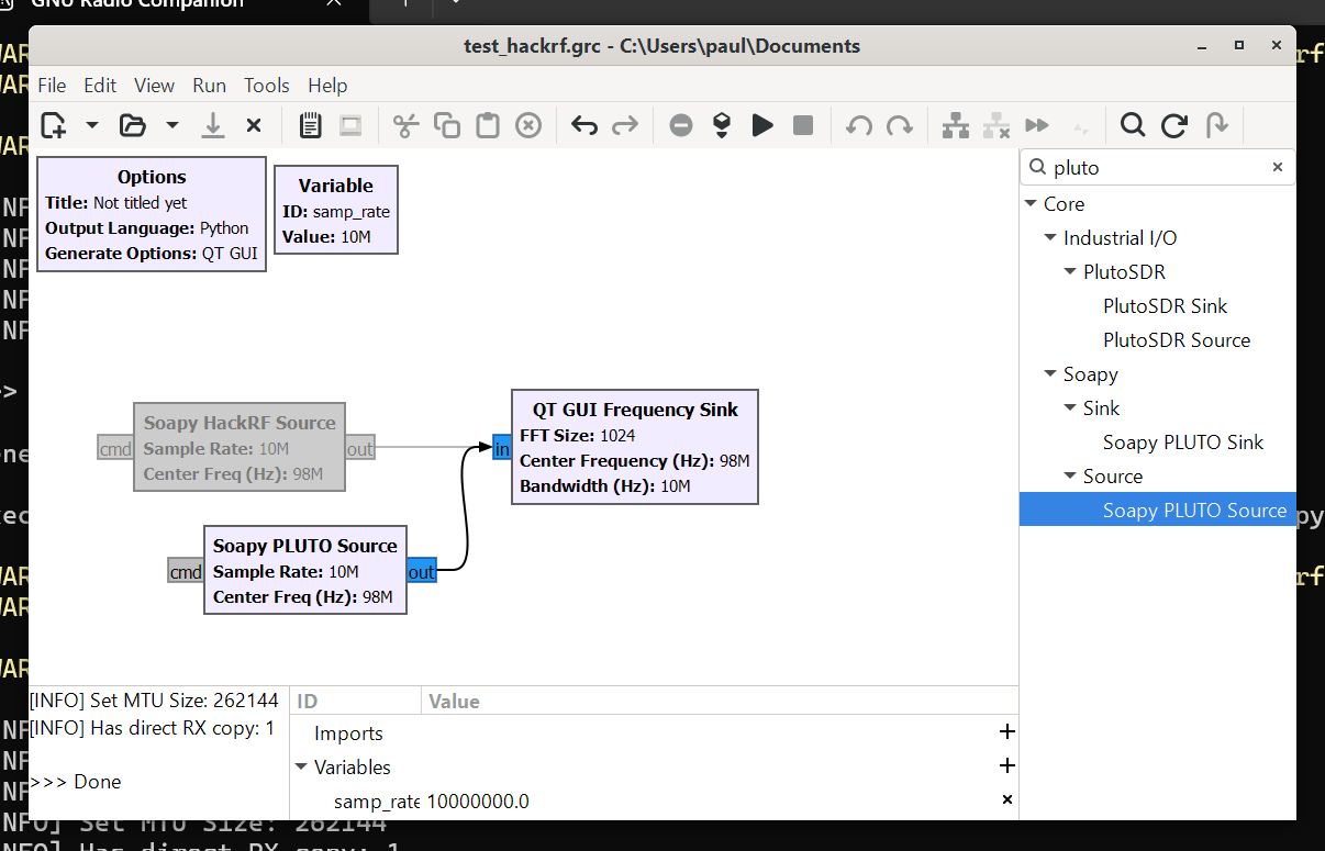
Create a flowgraph as follows:
- change existing samp_rate variable to “10e6”
- add a Soapy LimeSDR Source with
- RF Options -> Bandwidth: 0
- RF Options -> Center Freq (Hz): 98e6
- add a QT GUI Frequency Sink with
- General -> Center Frequency (Hz): 98e6
- Connect the source output to the sink input
- Save the flowgraph

Attach your LimeSDR to the PC via USB. After executing the flowgraph using the Play button in the toolbar, you should a live frequency plot several FM broadcast signals. The specific frequencies you observe will be different depending on the FM broadcasts in your area.


